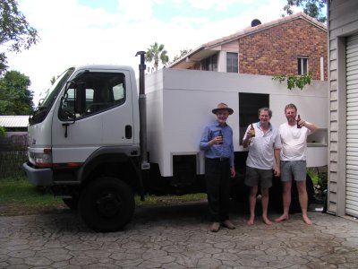
This is a brief description of the 6-7 month build project. It was mostly achieved with just one person working almost full time, 7 days each week. There was help along the way of course, absolutely essential for some parts. Thanks to Peter (Oka196), Ian and Dave. Always useful to have people who can say "that's silly".
The build was made easier by the previous Coaster bus conversion. All the major bits such as solar, cooker, heater, pumps, etc. were removed from the Coaster and reused. The dimensions of everything were available for planning as well as the experience of having fitted them previously.
Generally speaking it was a good project. Most things went to plan with no real surprises. A few frustrations along the way, and it of course took longer than expected. There were also countless cups of tea, which always arrived when things weren't quite right, or the glue was about to set. But yes, overall an essential ingredient, allowing time for thought and recovery.
- 4wd with gross vehicle mass under 4.5mt which can be shipped in a container.
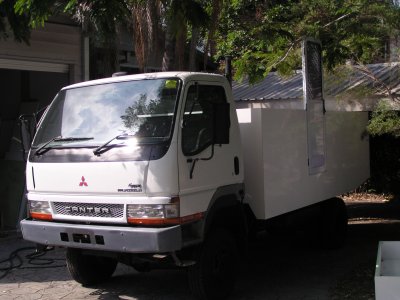
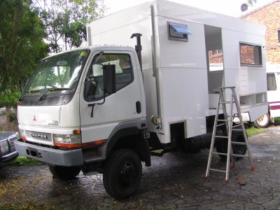
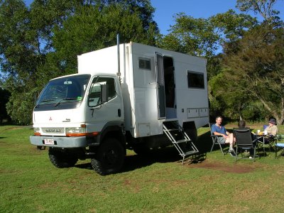
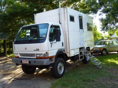
- based on Mitsubishi Canter 4wd MWB 2004 FG649E
- self contained and self sustaining. Diesel, fresh water, sunshine, and food in. Exhaust fumes, black and grey water, and waste packaging out.
- no gas, no normal requirement for shore power.
Layout
- drop top for occasional container shipping.
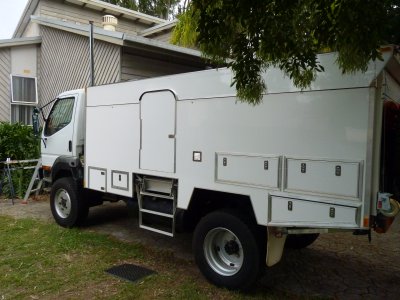
- central side door to reduce need for 2 people passing if door at one end.
- shower / toilet / cooking at front.
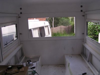
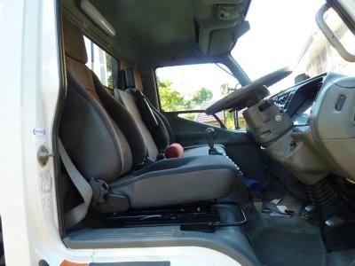
- comfortable seating with table at rear.
- East West bed raises / lowers electrically. Two seats usable when bed down.
- inner sprung, single sided, standard double bed size, mattress.
- third person can use seat squab on floor for sleeping
Electrical
- 12v electrics for vehicle and house.
- 225 Ah Fullriver AGM house batteries.
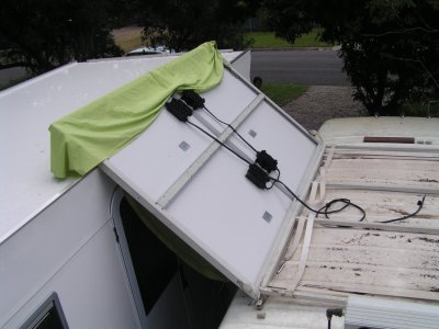
- solar, about 800w. Initially 340w from the Coaster, more added for overseas. Blue Sky MPPT 30A regulator. It doesn't matter that solar output is greater than regulator. We couldn't use it all. Our bigger problem is too little solar on rainy days, shade, and sun low in the sky. I'll maybe add a second 40A regulator some day. One reason for choice of Blue Sky was that more than one regulator can operate as one. Queensland floods interrupted the decision making.
- Sterling 50A battery to battery charger for alternator charging of house batteries if necessary while driving. Bypass switches for direct charging of house batteries from alternator, charging vehicle batteries from solar, or supplementing starting with house batteries. Sterling has increased his range and I would probably fit an alternator charger if starting again. Settings of solar regulator and alternator charging are such that solar is consumed first.
- mains battery charger for real emergencies.
- led lights throughout.
- diy vacuum insulated 150 litre fridge / freezer. 32Ah/day at 32ºC ambient, 24 Ah/day at 23ºC ambient. Danfoss BD35F compressor. Manual compressor speed control - normally on lowest speed (more efficient) but speed can be increased if required in very hot ambient temperatures (estimate above 35ºC) to reduce compressor cycle times. We normally avoid such temperatures. The efficient fridge is the key to sizing all of the electrics.
- Webasto X100 diesel cooker (ceramic top).
- energy requirement flexible.
- All appliances 12v (no 240v). 2x netbooks with 10 hour battery life and 12v chargers, 19" 12v tv with 12v satellite set top box (Australia Aurora decryption), all band Degen radio with rechargeable batteries.
- Satellite phone (Thuraya), NextG modem wifi base, wifi capable all band Nokia mobile phone (can operate as wifi hot spot). External 850mHz antenna.
- Compressor with good continuous rating connected to vehicle batteries.
Water / Heating
- About 180 litres fresh water. 60 litres grey.
- Water pressure 6psi. Two Shureflo 4 litre/min pumps, can run one or two. Separate industrial adjustable pressure switch, second contact to switch shower mixing solenoid..
- Collect water from roof. Fill from lake / river. Third pump to load lake water from bucket used for chlorine treatment. Inlet pressure regulator is modified toilet cistern float valve.
- Hot water calorifier. Heated from engine or Webasto (Thermo top E) diesel water heater. Space heating from engine or hot water heater. Engine preheat from hot water heater. Same for fresh water tank warmers.
- All water pipes lagged.
- Dometic VT2500 vacuum toilet. Two 14 litre cassettes accessible externally.
- Shower has tempering valve as hot water may be 80 deg C.
- Separate drinking water filter.
- Small cross section insulated sink. Washing dishes is probably the greatest use of water.
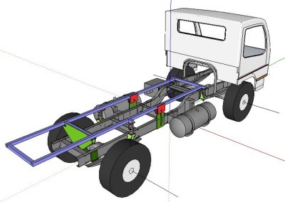
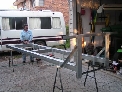
Google Sketchup is magic - once I'd figured out how to drive it. Significant sub-assemblies, such as the chassis, a fuel tank, the sub-frame, were drawn as components then "assembled". Drawing is directly as 3D. Neat.
Clearly shown here is the extra fuel tank and the sub-frame with its three point mount (pivot at rear) and 4 extra supporting springs. Apparently the rails and supports have to be at least partially above the main chassis rails. This is what the Engineer needed to approve and ultimately sign off.
Water tanks will fit within the sub-frame under the floor.
Basically the Canter has a relatively flexible chassis with relatively inflexible suspension. The chassis both twists and bends. A rectangular box body must be decoupled from the chassis.
The pivot was placed at the rear to minimise roll of the body relative to the ground. The pivot is also on the centre longitudinal axis of the chassis to avoid any lateral movement of the pivot induced by chassis twist.
Some attention was given to the effect of the body on suspension geometry, particularly being aware that vehicles with beam front axles can be more susceptible to roll steer.
The intent was to build a lightweight frameless box.
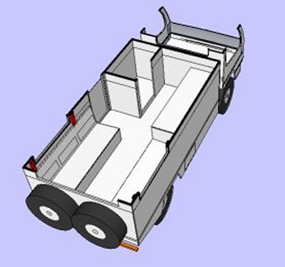
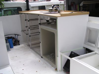
A simple layout. Shower / loo at front left. Kitchen bench at front right. Bench seats and table at rear, to take advantage of large rear window. The bed is transverse across the rear, electrical raise and lower (the red "legs").
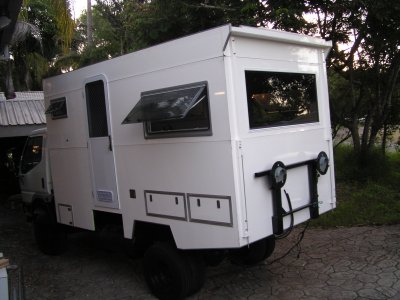
This layout proved highly effective. The finished vehicle was christened "Tardis" by some fellow motorhomers.
The internal "furniture and partitions" add to the structural strength of the box.
In any event, the huge access to the engine from tilting the cab was too good to give away or make more difficult.
Also, the extra weight over the cab would have made the vehicle nose heavy and probably exceed overall design weight.
The weight is fairly evenly distributed though I would have preferred the center of gravity to be further back. The vehicle is stable in side winds and when passing larger trucks.
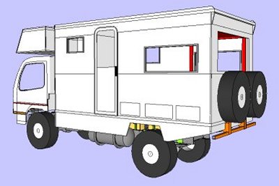
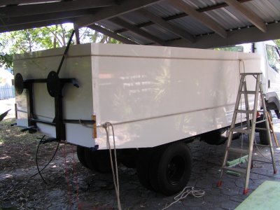
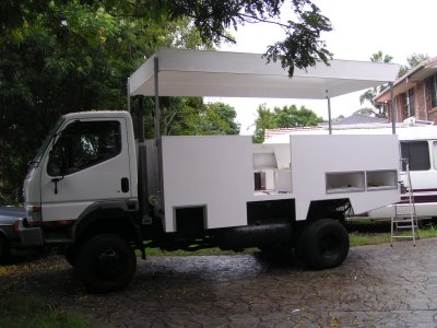
The horizontal lines below and above the windows is for the "drop top". the section containing the windows is removable allowing the roof line to be lower than cab height. It can be put in a 40ft HiCube container with about 2 hours effort.
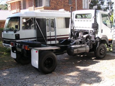
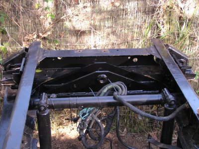
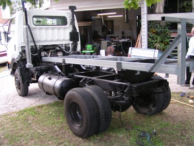
The tail section of the chassis was cut off by the previous owner. Just behind the rear spring hangers. If nothing else it provides a brilliant exit angle. It also meant that lengthening the springs to give softer suspension was not an option.
Driving it as a cab/chassis for 600km was bone jarring,. Even with tyre pressures much reduced. The bouncing of the rear end translated into a fore and aft motion at head height in the cab. Turning the radio on carried the threat of broken fingers.
The previous Coaster project, destined to supply most of the useful innards is behind the Canter.
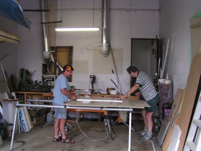
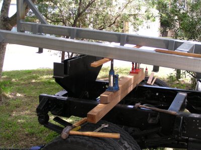
Sawn on a Triton Workcenter (a nice Aussie development). Essentially a very nice saw, and later router, bench with sliding table. Set up in our garage.
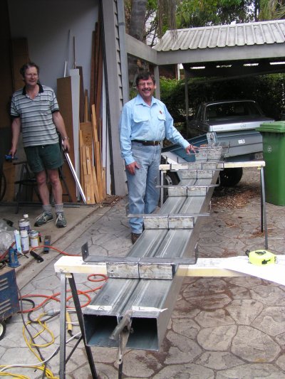
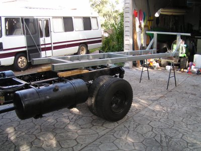
The tank hangers are all lined up ready for welding to the two sub-frame rails.
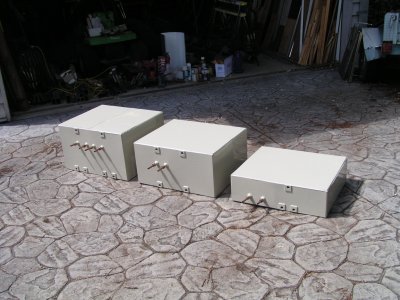
The left hand tank is divided in two. There are thus 3 fresh water tanks and one (smallest) grey water.
There are breather outlets at the top of each tank. Inlet/outlet and tank gauge at the bottom.
The pipes sticking out are the ends of copper pipe coiled internally for warming in very cold weather. The glands are lengths of polypropylene round bar with a hole for the pipe threaded for a normal olive fitting. There are no breaks in the pipe to fail. Did I mention I have a lathe.
The value of using Sketchup really sank in here as the tanks could be built in parallel with the sub-frame.
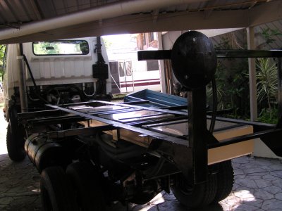
Its as square as we could make it (that's square and flat). The bits across the angle at the rear are bolted to allow the body to be built on the sub-frame. The holes were cut through floor and rear after they were installed. The bracing is hidden inside the under seat lockers.
There are additional tank hangers at the front end for a hot water calorifier.
The second fuel tank was also fitted while this sub-frame work was occuring. Electric changeover valve.
While it can twist with the chassis its not as flexible as the existing ladder sections and stiffens the chassis a little.
The pin is hardened steel in a bronze bush in a polyurethane bush in a steel tube.
The pin is held with a set screw. Unfortunately in haste the set screw wasn't located and tightened. This led to an exciting and nervous time during the first trip when the pin "walked" partly out and needed to be pushed back in. No damage, but could have been very much worse. In the plan was to drill a hole in the original rear cross member directly in line with the pin for just such eventualities. That wasn't done until after the trip which made pushing the pin back in a bit more awkward than it should have been.
That episode reinforced the need to investigate all strange noises or movements as soon as they are observed.
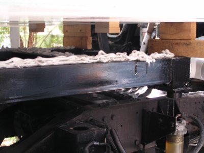
Just as attachment to the chassis rail are bolted onto the sides (there are no breaks or holes in the top or bottom of the C section) so the sub-frame rails are welded on the sides, not the bottom. Basic strength of materials (recollections from Uni Metallurgy course).
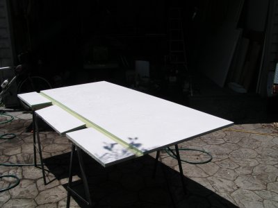
The panels were drawn as 3d components in Sketchup, including drawing the rebated joints.
It was simple to copy those components and re-assemble them as a flat sheet from which they could be cut.
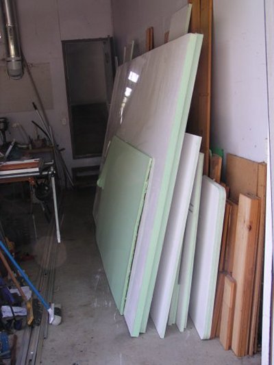
The panels are manufactured as 11m x 2.5m. Vanglas, the manufacturer, has a very large router.
File incompatibilities got in the way but it was relatively simple to redraw for the machine and let it cut the bits.
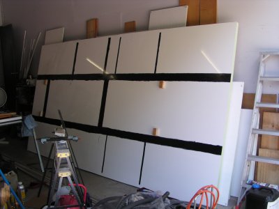
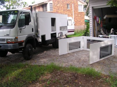
They arrived like some giant Ikea flatpak on the back of a small truck (easier than me collecting them).
Here stacked against the garage wall, roughly in the sequence in which they will be assembled.
The essence of laminates is that the strength is in the skin, the bit in the middle is just to keep the skins apart.
Also added are some external cross pieces to support and anchor the floor.
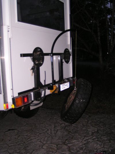
Spare wheel holder has also been added. Braces removed ready for body.
There are four blocks of wood glued to the floor to locate it on the sub-frame.
The floor is glued to the sub-frame using Sikaflex 252. The black is the primer for glass. The primer for steel was applied to the (unpainted) top of the sub-frame.
The floor is above, waiting to be lowered. Two of the locating blocks of wood can be seen.
Sikaflex works with large surface areas and reasonable thickness.
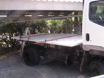
Floor has been glued to sub-frame.
While I was happy with just Sikaflex my Engineer twisted my arm and there are bolts (with large "washers" through brackets on those wings. At this stage clamps were used to maintain the gap for the Sikaflex.
After 5 months of Central Australian corrugations and tracks there is no sign of the Sikaflex giving way or of compression of the fibreglass by the through bolts.
There's always a risk in designing and building "one-offs". The important bit is to understand them as completely as possible before building.
Ian in the picture again.
There is a rebate into which the floor locates.
The cuts are to fit over the main sub-frame rails.
The router cuts to within a few mm of the under side of the panel. Foam was scraped out of the rebate with a chisel - then vacuumed up.
This was the first glued joint with Sikaflex 11-FC. Used rather than resin as it stays in place whereas resin tends to run, and drip, and make a mess.
We did check that the truck can be driven out of the carport after assembly. We had a few mm to spare!
The fan is because it was hot weather.
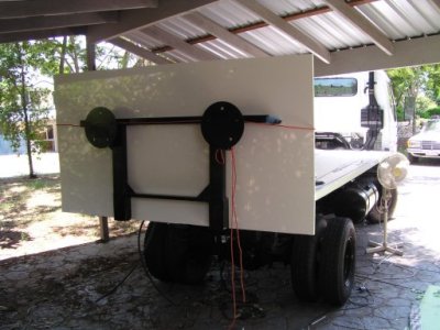
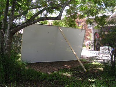
The roof is like the floor. There's a lip of the sides all the way round above the roof so that rainwater can be collected.
Here the roof is upside down. The blocks of wood on the corners are cutout so they don't move. The rope was tensioned by twisting.
Some things, like exact position of the wheels, were difficult to measure to get the drawings right. So wheel arches were cut later.
A nervous moment, but it worked.
The foam around the door has to be removed and wood glued in to provide something for the door to be screwed into.
One of the problems with building a frameless fibreglass panel body is that accessories are designed for other manufacturing techniques.
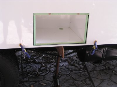
Zed section Aluminium extrusions will be glued around the entrance.
This particular hatch really needed to allow water to flow out, so no lip. An interesting arrangement of jack, clamps and webbing to hold it together while gluing.
The piece removed is used for the door. The theory (and practice) is that relatively rigid doors don't flex, the hatch doesn't breathe, and there is little dust ingress. Add a bit of rubber foam seal and everything is clean.
The doors will be attached with piano hinges along the bottom and lockable (keyed alike) compression latches at the top.
The edges of the doors will be sealed with "Kube Lok" 25mm hollow square Aluminium slit lengthwise to be a channel. Glued with, you guessed it, Sikaflex 11-FC.
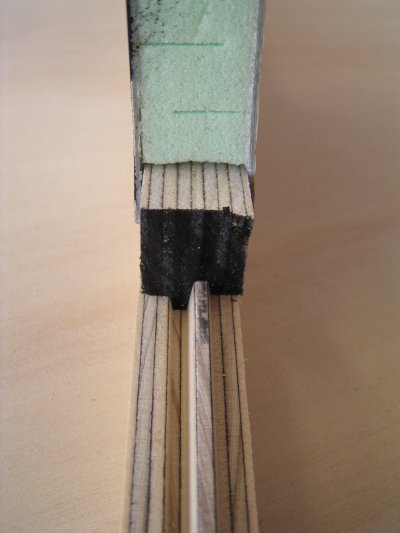
Made from marine ply. The spec for marine ply is mostly about no voids and good surface rather than glue. Both parts cut with the same router bit.
I chose a tongue and groove with angles rather than straight sides so it will come apart more easily. One hopes!
The right of the picture is the outside.
Ply is not an engineering material. Local ply supplier humoured me and allowed me into the warehouse with vernier calipers to select the thickness I wanted. It would have been nice to have a pultrusion, but not practical in the time frame for a one-off.
Made a "special tool" to dig out the foam. A chisel with a couple of bits of steel angle bolted on so it operated like a plane that cut a deep groove.
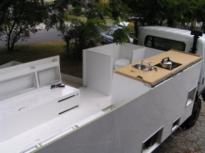
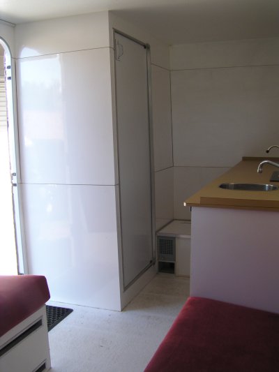
Loo and cassettes installed.
Batteries are in their compartment (next to door). The vents are to allow cooling for solar regulator and battery to battery charger. That and distribution / switchboard are separate to battery compartment which is vented to outside.
Diesel cooker and water heater installed. Bits transferred from the Coaster.
Plumbing in place.
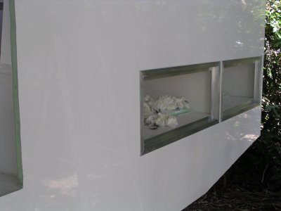
Foam removed ready for plywood joint.
Fridge is vacuum panel insulated. Very efficient.
Space heater (bottom right) is connected to engine / diesel heater circuit. Fridge compressor behind it.
Drawers and shower door will be made with Dibond. A sandwich of polyethylene between 0.2mm stove enamelled Al. It can be folded by routing a V groove. The edges can also be welded. The shower door is recovered from the Coaster.
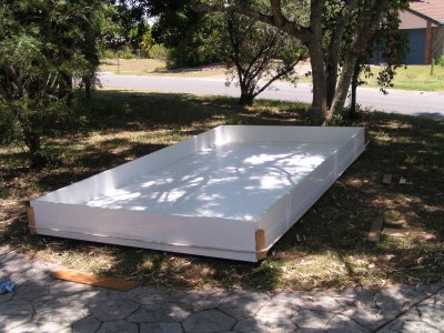
Ali and I managed that with the help of a strategically placed piece of wood.
Pity about the grass. It grew back! Not everyone has a motorhome roof on their front lawn.
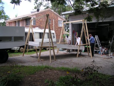
Lift the roof up Drive the truck under. Lower the roof.
Ease!
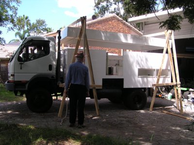
And of course the ever present "will it fit?".
A good outcome. Probably the result of the combination of sufficiently detailed drawings, the router that cut the panels, and my usual good luck.
Dave, Ian and I relaxed after a not so difficult hour.
There's two over centre catches (from the marine store) at each corner to hold things together during assembly.
It means one person can raise and lower the roof and attend to the sides.
The windows are standard Dometic. Double glazed acrylic. We expect to have to polish them every so often.
Each leg is two bits of hollow square steel. A pulley at the top of the bottom leg. Hand winch at the bottom. The wire rope describes a sideways "S" anchored to the bottom of the top bit of steel.
One turn at a time, walking round and round.
It didn't take long. Looks like we are ready for a safari.
The legs also have a long threaded rod which compresses the roof onto the walls - a very important part of keeping the whole box rigid.
Another nervous moment as they have to be inserted through the slots that were cut in the back of the seats before they were glued in.
A real test of the drawings. Its always possible to draw things which can't be assembled.
Its also a test of whether its all going to be waterproof as there was rain about.
The stands for the bed legs can now be installed to get the bed to the right height.
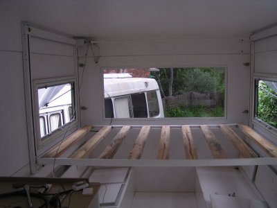
The wooden slats were eventually replaced with fibreglass panel, once satisfied that it wouldn't collapse.
The bed is standard double bed size, deliberately, which made buying a mattress really easy.
Sketchup worked again. The bed was moved on the drawing to check the clearances.
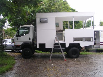
The extrusion used to seal the raw foam edge around the roof is also in place.
Finding extrusions was extremely difficult. I used Kube Lok cut lengthways on that wonderful Triton saw bench. It fitted perfectly, glued with Sikaflex.
Same was used around the bottom edge.
Hatch doors in place. Beginning to look real.
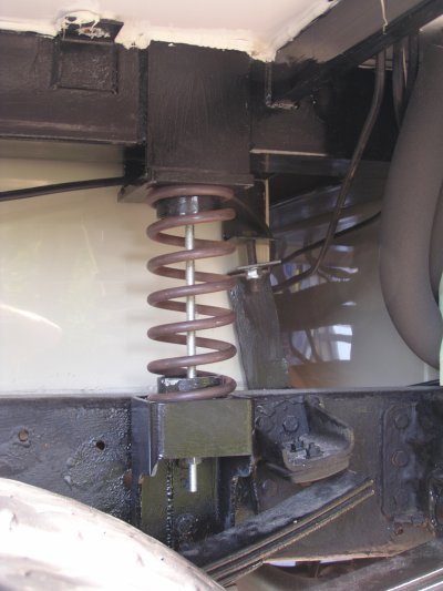
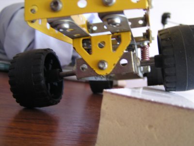
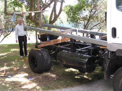
They aren't for suspension. They are there as extra load support. They are long enough that for the small movement involved they give almost constant support.
They were fitted by unbolting the bottom holder from the chassis, inserting the spring, then using the centre bolt to compress the spring.
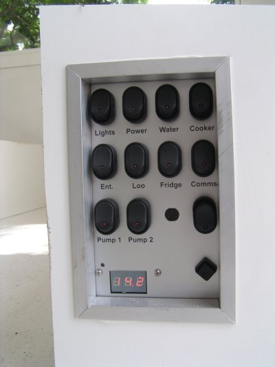
The switches have leds in them. The diamond shaped push button switch at bottom right is to turn all the leds off. Phantom loads in a solar electrical system can soon consume a lot of energy. At this stage I was one switch short. All circuits are individually fused and there's a single large circuit breaker close to the batteries.
The 14.2 is solar regulator volts to the batteries.
Charging is from solar and/or battery to battery charger from engine alternator.
There is no 240v. Also no gas (diesel cooking and water heating).
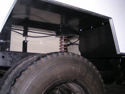
Those "wings" off the sub-frame came in useful after all. They were cleverly positioned to give the wheel arches something to be bolted to.
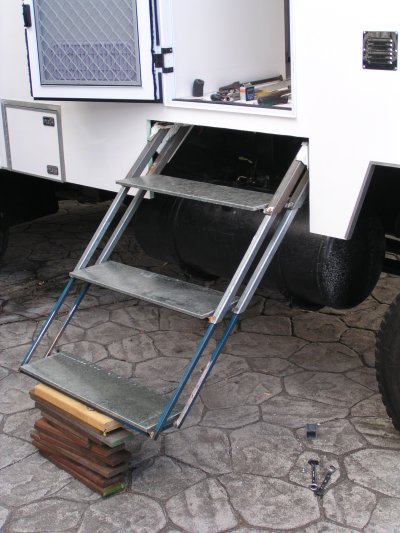
They worked well but tended to get stuck a bit (forgot to have something at the top of each leg to make it telescope straight) and really needed 4 steps instead of 3.
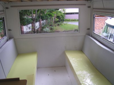
The foam for the squab is more resistant than that of the back.
The angles of squab and back were copied from our very comfortable settee after much research.
Later, when showing the vehicle off, a group of 5 ladies sat and talked for a couple of hours. I figured if it was uncomfortable they would have moved. A good test. We've found it really comfortable.
Like lots of people I have a back problem. The seats work!
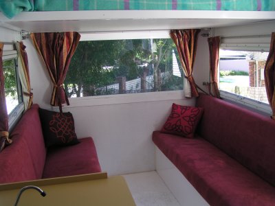
Getting to be a real home from home.
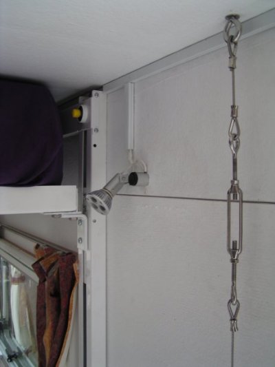
This bit of wire rope, one on each side about midway, creates tension between the floor and the roof. It improves the rigidity of the structure, particularly around the door.
Apparently the Sydney Opera House is also post tensioned. There are wires through the main arches, without which it would all collapse.
Not so dramatic in our case but a well understood engineering solution.
Time to add that the legs that raise the roof also have tensioning in them to hold the roof down and give the structure rigidity. Very important.
From an idea of Peter's. Implemented on his Oka. The wire from the brake winch passes through the rounded pipe.
The tyres are the large Michelins. Later replaced with bigger rims and Toyos after a minor hassle with engineering approval.
The build took 6-7 months.
The vehicle has a Gross Vehicle Mass (GVM) of 4495kg. This is quite useful as in Australia it is not a heavy vehicle and in Queensland doesn't require an annual inspection. A definite plus as the plan is to take it overseas. It can also be driven on a car licence.
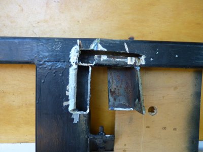
This is what was left once the holder had been removed.
A bit of steel, a bit of welding, a bit of extra bracing (to stop the spare wheel behaving like something on the end of a stalk in the wind) and it was a relatively easy repair.
I guess something had to go wrong!
Turns out our friends at AllTerrainWarriors are familiar with fitting both passenger and driver side as well as retaining that important little seat in the middle. Important for our Chinese guide (not as it sounds, we just need three seats).
First impression is that the vehicle travels faster, we'll have to be careful. In the 5 months trip we weren't conscious of bottoming out the suspension (perhaps only 4.5mt on suspension designed for 6mt).
The crawl through is a casualty of the Queensland floods which consumed much of our time.
The new steps are still stiff. And they slide out on drawer runners rather than being unhooked as per manufacturer's intent. The ladder arrangement under them is for easier access when steps are up.
For the really observant there are a couple of new holes in the front bumper. I added four recovery hooks bolted to the chassis and that was the only way of providing access.
There are a couple of extra lockers. The water pumps and manifolds have been moved under the floor to that new locker just to the left of the steps. Quieter inside and out, and better priming from the tanks. Also additional valves to allow isolation of plumbing sections in case of leaks. Left more space for veggies inside. Also two lockers behind rear wheels under the floor.
A couple of telescopic legs behind the rear wheels.
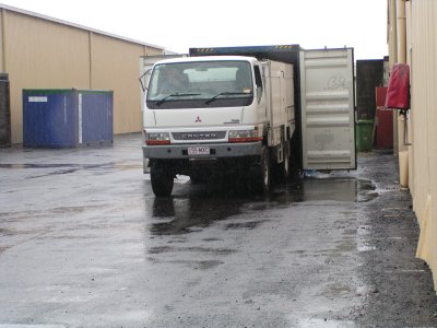
Container ready. It will be shipped to Malaysia.
Mirrors, exhaust and air inlet will be removed just before putting it in the container.
The doormat goes inside!
He volunteered to be inside so I handed him the radio.
Lo ratio 4wd (without the hubs engaged). Line it up from about 30m away. There's 125mm each side. 25mm more than we thought.
The vehicle crawled so slowly that it was easy to see and correct to keep it straight.
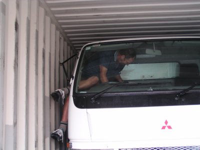
A bit of a contortionist act. I'll remove the last of the mirror bracket next time. The door is a bit curved so I had to squeeze around the front with a foot on the bumper bar. My head just fitted under the bracket.
Perhaps I should mention I had a bit of practice in a time long ago. A bit of potholing (speleology) and climbing.
Hopefully getting back in is as easy.
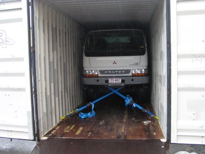
There was so much room either side I felt it unnecessary to add dunnage bags.
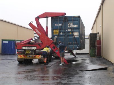
Much better than a forklift!
More to follow when we take it out of the container in Malaysia.